
Hiii,I am Sk.riyaz basha. I have Completed my sevel engineering.but I am interested in electronis because i love technology,and solar energy and nano technology.Reading books,writing poems,talking with different people ,traking are my hobies.After complecte sevel engineering I have started learning with Vigyan Ashram as a D B R T [Diplama in basic rular technolagy].
This
is my self .now startet my project information .
What
is Polyhouse ?
A
polytunnel (also known as a polyhouse, hoop greenhouse or
hoophouse, or high tunnel) is a tunnel made of polyethylene,
usually semi-circular, square or elongated in shape.
What
is automation poly house ?
The
main goal is to
build
a miniature polyhouse which is equipped with
an
automatic monitoring system. This monitoring
system
will constantly monitor the conditions in the
polyhouse
to ensure that it remains a
t
preset
temperature
,
light
humidity
conditions.
If
these conditions differ from the preset levels, the
monitoring
system will automatically turn on certain
devices
to return the polyhouse to the required
conditions.
Automatically
control the crop
growing
environment
within
the walls so that
any
type of plants can be
grown
all year round. Eliminates the risk of the
polyhouse
not being kept at crop specified conditions
due
to human error. Minimizes the labor costs crop
involved
in maintaining a playh
ouse.
Customer will
be
able to define their crop preferred polyhouse conditions and have the
system function as specified.
This
will be a “plug and play” product.
What
is the main difference normal polyhouse and automation polyhouse
Normal
polyhouse :Polyhose is normal iroan structure and coverd some
polythin covers and
saporting some
galavanized pipes .
A
polytunnel (also known as a polyhouse, hoop greenhouse or
hoophouse, or high tunnel) is a tunnel made of polyethylene, usually
semi-circular, square or elongated in shape .
automation
polyhouse : If the temperature exceeds the maximum
value,
the plc will then turn on the fan. If the
temperature
drops below the minimum value, the
bulb
will turn on. As for the photodiode, if the
polyhouse
is exposed to insufficient light,
it
will send
a
signal to the plc. The plc will then process the
signal
and turn on the artificial light in the polyhouse.
As
for the humidity sensor, it will detect a change in
humidity
levels of soil and send a signal to the plc. If
the
humidity level is
not
within the required range,
the
water supply will be turned on or off. The plc will
be
the central processing unit which will translate the
input
signals from the sensors and turn on or off the
necessary
devices to maintain the polyhouse at the
preset
levels.
“To
maintain environmental conditions inside the
house
for better production of crop with the help of
PLC
which make it suitable for productive uses and
help
improve crop quality and quantity.”
SYSTEM
IMPLEMENTATION:
Programmable
Logic Controller
We
will use Arduino uses 12V dc power supply.
Actual
programming is stored in the Arduino microcontroller.
Matireal
requerd :
We
will use humidity sensor for sensing the
humidity
of soil. After that this
signal
is
send
to plc. In that plc a particular set point
is
given and if it is below or above it take
action
likewise .
Temperature:
We
will use thermocouple as temperature
sensor.
Temperature is sense an after that 
this
signal is send to Arduino. In that plc
a
particular
set point is given and if it is below
or
above it take action likewise.
Exhaust
Fan:
The
fans should deliver the required air
at
15mm static pressure. The maximum
center
to center spa
cing
between the two
fans
should be of 7.5m. The height of the
fans
is to be determined based on the plant
height
which is proposed to be grown in the 
greenhouse.
The fan blades and frame are to
be
made of non
-
corrosive
materials like
aluminum/stainless
steel .
humidity control :
humidity control :
:
The
humidistat coupled to water
circulating
pump to control the relative
humidity
of soil. Here we maintain the
relative
humidity of soil. This is one type of 
watering
system in this soil sensor is use to
find
out humidity
in
soil and if it is less then
motor
pump start and water is giving to the soil .
230
volt motor :
The
motor on will be moistuer <700 and motor offautomatically
>300
soil moistuer .
will
be switch in normally close to normally open .
Main
heart was this project arduino because arduino will be send a
signel
relay and some kind of sensors Exm : tempreatuer & moistuer
LCD :(liquid crystal display)
LCD (liquid crystal display) is the technology used for displays in notebook and other smaller computers. Like light-emitting diode (LED) and gas-plasma technologies, LCDs allow displays to be much thinner than cathode ray tube (CRT) technology. LCDs consume much less power than LED and gas-display displays because they work on the principle of blocking light rather than emitting it.

2Channel relay module

The Arduino Relay module allows a wide range of microcontroller such as Arduino, AVR ,PIC, ARM with digital outputs to control larger loads and devices like AC or DC Motors, electromagnets, solenoids, and incandescent light bulbs. This module is designed to be integrated with 2 relays that it is capable of control 2 relays.The relay shield use one QIANJI JQC-3F high-quality relay with rated load 7A/240VAC,10A/125VAC,10A/28VDC.The relay output state is individually indicated by a light-emitting diode.
- COM- Common pin
- NC- Normally Closed, in which case NC is connected with COM when INT1 is set low and disconnected when INT1 is high;
- NO- Normally Open, in which case NO is disconnected with COM1 when INT1 is set low and connected when INT1 is high.
- INT 1- Relay 1 control port
- INT 2- Relay 2 control port
Arduino is an open-source electronics platform based on easy-to-use hardware and software. Arduino boards are able to read inputs - light on a sensor, a finger on a button, or a Twitter message - and turn it into an output - activating a motor, turning on an LED, publishing something online.
iam using this arduino uno because this is able to read inputs -light on a sensor.

Proses in this project :
First i am connect a LCD connections because LCD was a main part of this project.
Easy to identify which load is on or off at this time .
which sensor will be work or not i am easy to identify help with LCD only . so first
i will sagest to connect a LCD connections .
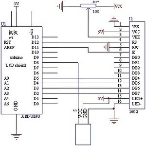
Now i can tell you LCD connection with circuit diagram :
LCD Connections with Arduino uno
Before wiring the LCD screen to your Arduino or Genuino board we suggest to solder a pin header strip to the 14 (or 16) pin count connector of the LCD screen, as you can see in the image above.
To wire your LCD screen to your board, connect the following pins:
- LCD RS pin to digital pin 12
- LCD Enable pin to digital pin 11
- LCD D4 pin to digital pin 5
- LCD D5 pin to digital pin 4
- LCD D6 pin to digital pin 3
- LCD D7 pin to digital pin 2
More information for LCD connections with arduino
https://www.arduino.cc/en/Tutorial/HelloWorld
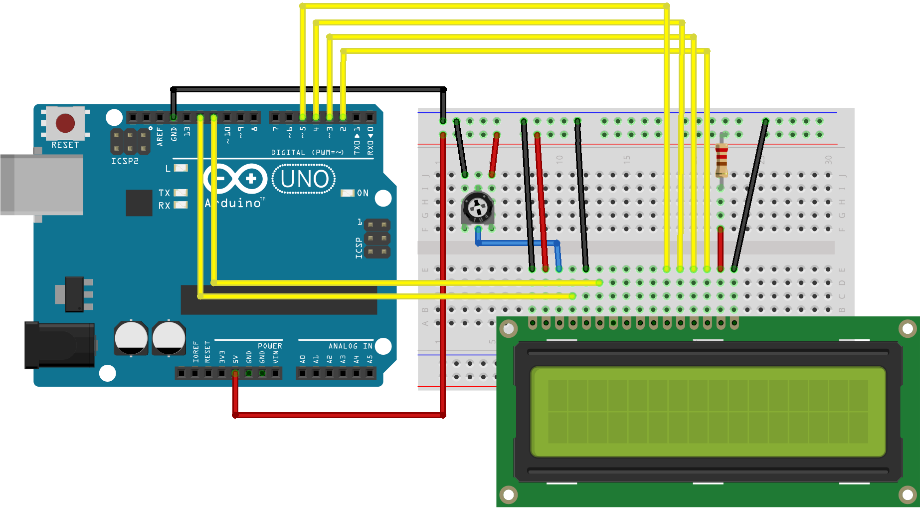
Now connect a LCD with aruino look like this .
DHt-11 sensor connections with arduino uno :
It's time to connect a temperature & humidity sensor with ardino
First i can show a circuit diagram
Temperature connection is a too easy with arduino
DHT-11 sensor had a three terminals
1. vcc
2.ground
3.data
*Now connect a sensor vcc & ground pins with arduino.
* i am define a data pin a arduino 6 no pin .
So this is a arduino connections .
you want a more information open this link
http://www.getmicros.net/arduino-dht11-sensor-example.php.
you can complete a connections look like this

After complete look like thise
Moisture sensor connections with arduino uno :
Now connect a Moisture sensor with ardunio
Ok first i can show circuit diagrem with arduino
the moisture sensor connections its too easy because this sensor have a
only four terminals but i can use a three terminals .
Pin Assignment
There
are 4 pins used to interface Moisture Sensor board to arduino.
User may used either Digital Output (DO) or Analog Output (AO) or both
pin as output pin.
- VCC
- GND
- Digital Output (DO)
- Analog Output (AO)
i am define data arduino pin 9 .
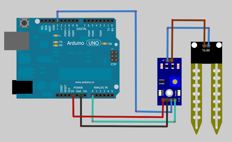
After connect look like this
Example Code
// Soil Moisture Sensor Hygrometer example code
// Code author: http://electron-space.blogspot.com
// Interface Description (4-wire)
// VCC: 3.3v-5v
// GND: GND
// DO: Digital output interface (0 and 1) threshold taken from potentiometer
// AO: Analog output interface
const int moistureAO = 1;
const int moistureDO = 13;
int AO = 0;
int DO = 0;
int tmp = 0;
void setup (){
Serial.begin(9600);
Serial.println("Soil moisture sensor");
pinMode(moistureAO, INPUT);
pinMode(moistureDO, INPUT);
}
void loop ()
{
tmp=analogRead( moistureAO );
if ( tmp != AO )
{
AO=tmp;
Serial.print("A=");
Serial.println(AO);
}
tmp=digitalRead( moistureDO );
if ( tmp != DO )
{
DO=tmp;
Serial.print("D=");
Serial.println(DO);
}
delay (1000);
}
you wan a more information see this link
https://docs.google.com/document/d/1Z5C1MgRsdo8y6ipWAQN2y7p9sYSn-G3oF8FhCulNeAk/mobilebasic
Which loads connect with sensors
1.temperate sensor connect Exhaust Fan .
2.Moisture sensor connect a drip irrigation system .
3.LCD connect connect a each too sensors .
Testing of process wiring and troubleshooting
The crux of all troubleshooting was testing
of through process wiring. The entire system had to
be connected to the arduino. In numerable problems
were encountered in this process specially like. Wire
not been connected to the proper port. Wiresall connected at wrong points either on the junction boxand terminal strips. Few instruments were notconneted to the arduino.
Testing of pump and automatic
-
The pump had to be tested for its working
and efficiency. We also needed to automate the
pump. The pump is automated by connecting a relay
of 5V to 230V so that once you connect the pump
wiring to the relay, the pump starts as soon as a 5v
signal is given to it by the PLC.
result
In this way we maintain the environment of
polyhouse using arduino and sensors.
In this way after taking lots of efforts
we are
successful to make automated Polyhouse. arduino
have some Digital as well as some Analog input
after sensing them it will take the decision as per
ladder logic and handle number of digital outputs
for polyhouse.
Due to automation there is no necessity of
number of worker to handle farm. Only one trend
person will easily handle the polyhouse.
In this project i can say this polyhouse is nota easy as it seems . It has great importance as a form as well as i society During this project we realize that environment control processes are very precise well controled .using arduino techniques we can automate the whole polyhouse.
As we see crop is one of the one of the importance
and to increase the crop polyhouse is best option .in this way we will make automated polyouse using arduino .An we provide farmers a new wold of technology ,because of this project farmer will become rich and everyone who think that forming is
form villag people ot illiterate people they will also do farming ad improving this system .
Block diagrams


Final project photos


Prototype photos

Final project look like this

Out side of polyhouse look like this
Programming time


Prototype photos

Final project look like this

Programming time


0 टिप्पणी(ण्या):
टिप्पणी पोस्ट करा