Incubation process of chicken
- 1. Contents
- 2.Incubation & its Types
- 3. Obtaining hatching eggs
- 4.Storage and care of eggs prior to incubation
- 5.Location of incubator
- 6.Readying the incubator for operation
- 7.Preparing the eggs for incubation
- 8.21st day developmental stages of embryo
- 9.Final stage of incubation
- 10. Factors affecting the incubation
- Incubation : “The process of changes of fertile egg to a living organism capable of walking and eating. Through Natural incubation at small scale using “Broody Hen” and Artificial incubation at large scale for the commercial purpose using different machines called “Incubator”is called incubation.
- Types of Incubation :There are two types/methods of incubation 1. Natural incubation (Broody Hen) 2. Artificial incubation (Incubator)
Now i can talk with Natural incubation
Natural incubation (Broody Hen) The Broody hen is a time tested way to hatch eggs. Very good at her job. To use a hen for hatching you have to do one of two things Find a hen sitting. Induce a hen to sit .
Natural incubation (Broody Hen)
Signs of broodiness
Clucking
Stays away from the rest of the flock
Ruffled feathers
Aggressive and protective of nest
On the nest at night .
Natural incubation (Broody Hen) Characteristics: No electricity required Hen does all the work herself Will brood chicks after they hatch. High hatchability rate Some breeds hatch better under hens (Nankin) than in incubators. Good for hatching small # of chicks per year.
Cont…
Drawbacks:
Can only sit on a small # of eggs at a time.
Hen sometimes breaks eggs.
Will occasionally quit and get off nest.
Disease transmission from hen to chick 10
Artificial Incubation Incubator
An incubator is basically a box that holds eggs while maintaining appropriate temperature, humidity, and oxygen level.
Incubators have varying capacities and adapters for eggs from different species
Popular incubator models often include
Automatic turners
Humidifiers, and Temperature controllers
Artificial Incubation
Incubators comes in
Forced air incubator
Still air incubator
The temperature and humidity in a forced air incubator is more consistent. They also return to desired temperature and humidity more quickly after being opened.
Still air incubators can give inaccurate humidity and temperature readings and the temperature in them can vary considerably.
Preparation Stage
Chick incubation process is 21 days
Gather fertilized eggs 2 – 3 days in advance
Grading and cleaning of eggs
Storage of hatching eggs
Disinfection of hatching eggs
Location and set up of incubator
From Egg to Chick:
Incubation Procedures
1. Obtaining and caring of eggs
Gather fertilized eggs from a disease free breeder farm
2. Grading and cleaning of hatching eggs
In selecting hatching eggs, the requirements regarding shell quality and egg shape will be higher for layers than for broilers.
Eggs unfit for hatching are
dirty eggs
Cracked eggs
thin shelled eggs
eggs with shells, which are rough and not uniform
misshapen eggs
eggs with abnormal spaces - loose or floating air cells
too large air cells
Location and Preparation of incubator
The incubator should be in a room that has
No drafts
No direct sunlight;
The temperature (85-99°F ) and humidity should be controlled and stable.
The incubator and hatcher should also be isolated from the growing facilities.
Cleaning and Sanitation of incubator
Sanitize the incubator with detergent or with the combination of detergent and disinfectant and run it for several days before setting the eggs.
* This will ensure that the incubator is maintaining the proper temperature and relative humidity 2-3 before the eggs are set.
Adjusting the temperature and humidity after the eggs are set can decrease hatchability.
Preparing the eggs for incubation
To ensure proper turning, mark all eggs on one side with an “x”, the other side with an “o” 21 .
The day eggs are set
Let stored eggs warm to room temperature for 4 hours to 8 hours before setting them in the incubator.
If you place cold eggs in a warm, humid incubator, condensation will form on them and lead to possible contamination or suffocation.
Once the eggs are in the incubator, do not adjust the temperature or humidity for a few hours, unless the temperature exceeds 95 to 99°F.
Cont…
After 4 hours, make proper adjustments. The final temperature should vary only 0.5 degree above or below 99.5°F.
The development of the embryo can roughly be divided into the following stages:
a. In the hen : three layers of cells
b. During incubation:
1st - 4th day : initial stage of inner organs
5th - 14th day : initial stage of outer organs
15th - 20th day : growth of the embryo
21st day : hatch of the chicken
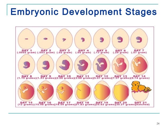
Summary of the embryonic development from day to day.
Stage I: Development of the internal organs
1st day : enlargement of the blastodisc
2nd day : heart starts beating, tiny bloodspots appear
3rd day : initial stage of the beak, legs, wings
4th day : initial stage of the tongue
5th day : shaping on the reproduction organs
Stage II:Development of the external organs
6th day : beak gets shape
8th day : shaping of the feathers
10th day : hardening of the beak
13th day : shaping of the leg scales and claws the size of the allantois reached its maximum
14th day : the structure of the embryo is completed the embryo settles for its final position .
Stage III: The growth of the embryo
15th day : leg scales and claws become horny from the 15th – 19th day the intestines are withdrawn into the body cavity. The neck bends forwards
16th day : the contents of the allantois has disappeared completely
17th day : the beak directs itself toward the air cell the fluid of the amnion continues to disappear. This will be finished at the 19th day .
Cont…
19th day : the yolk is being withdrawn into the body cavity the air cell gets penetrated by the beak
20th day : the yolk is withdrawn, the embryo fills the whole egg, excluding the air space the eggshell is fractured
21st day : the chicks is hatched .
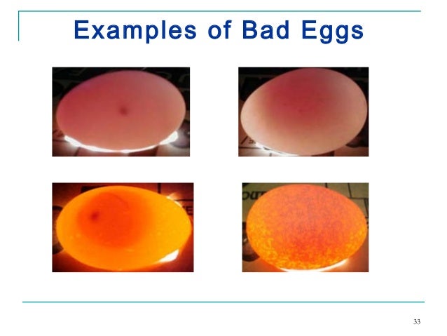
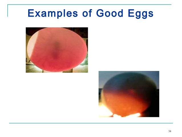
Candling “Shining a light through the egg to observe embryo development is called candling.”
White or pale eggs are easier to candle than dark or spotted eggs.
Embryos can be confirmed easily after 8 to 12 days of incubation.
Candling
The living embryo will appear as a dark spot in the large end of the egg surrounded by a faint outline of blood vessels.
The embryo appears as dark spot that becomes larger as incubation progresses.
Eventually you will see only a dark mass and the air cell.
Candling In comparison,
An infertile or un-incubated egg transmits light brightly.
Dead embryos will sometimes appear as a ring or a smear of blood in the egg or a dark spot dried to the inside of the shell.
Once it dies, the embryo no longer grows and the blood system fades.
Cooling that occurs for less than 10 minutes during candling does not harm the embryo.
Hatch stage
This stage refers to final 2 to 3 days of incubation when chicks hatch out of the shell.
Transfer eggs to a dedicated hatcher for the last 3 days to 4 days of incubation and do not turn them.
During this stage, decrease the temperature 1°F and increase the relative humidity to 65- 70%.
You can increase the humidity by adding a wet sponge or wet paper towels to the incubator.
Final Stages of Incubation
After the 17th day...
Eggs should not be turned
Incubator should not be opened unless it is necessary to add water
Chicks will start to pip the shell around the 19th day.
All chicks which are going to hatch should be out of their shells by the 21st day
Managemental factors for the incubation and hatching process
For a special incubation and hatching the following factors are of major importance:
1. Temperature
2. Humidity
3. Ventilation
4. Turning
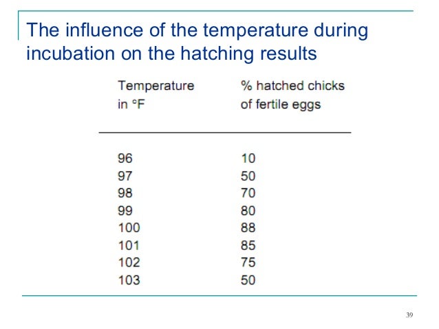
Temperature
During incubation till 18th days the temperature should be 99.5◦-100◦ F.
In the hatcher the temperature should be 98.5 - 99◦ F.
Make sure of a constant temperature and regularly check the thermometers of deviations.
Too high as well as a too low temperature has influence on the hatching results.
Check the temperature at least twice a day.
 Humidity
The ideal moisture level is about 50 – 55% relative humidity (83o - 87o F (28 - 31o C) on a wet bulb thermometer) for the first 18 days.
About 65 % (89o - 90o F (31 - 32o C) wet bulb) for the last 3 days.
Excessive drying because of low humidity will cause the chick to stick to the shell and fail to survive. To increase the humidity level the last three days, set an extra pan of water in the incubator.
Humidity
The ideal moisture level is about 50 – 55% relative humidity (83o - 87o F (28 - 31o C) on a wet bulb thermometer) for the first 18 days.
About 65 % (89o - 90o F (31 - 32o C) wet bulb) for the last 3 days.
Excessive drying because of low humidity will cause the chick to stick to the shell and fail to survive. To increase the humidity level the last three days, set an extra pan of water in the incubator.
Turning the eggs
During the incubation period (1-18days) the hatching eggs need regular turning (90o ) to prevent that the embryos from sticking to the shell membranes.
As it will do if it is left in one position too long.
Turn the eggs at least (10-12) times a day.
Cont…
Temperatures too high, too low, or too variable during incubation
Too little humidity in the incubator or occasionally too much
Improper ventilation
Oxygen starvation
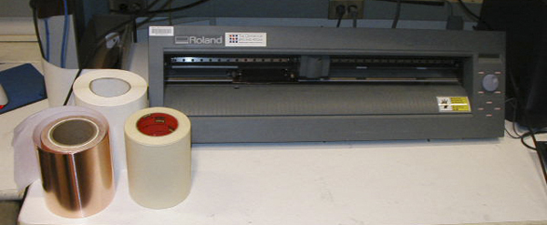
Naw make a Automatic Egg Turner
First thing you have to know about me is I am NOT going to spend any big money on anything. I can always make it myself, with a little help from my friend also sir. We are remodeling so I just so happened to have cabinets laying around taking up room. I also just happened to get addicted to chickens about the same time. So now that i have my bigger chickens settled into their new coops/pens I just had to start a new project. So first things first the cabinet. It is a 30" base cabinet that had sliding trays we are using for the egg turner trays.
What we need
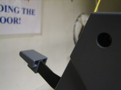
This motor is a 10 RPM 12V DC motor for the IncuKit DC. Use this motor to make your own egg turner. The IncuKit DC allows you to set an interval so the motor will turn on for a few seconds every few hours (Customize to your own turning needs).
RTC module
This a link How it's work
http://tronixstuff.com/2014/12/01/tutorial-using-ds1307-and-ds3231-real-time-clock-modules-with-arduino/
We keep getting requests on how to use DS1307 and DS3231 real-time clock modules with Arduino from various sources – so this is the first of a two part tutorial on how to use them. For this Arduino tutorial we have two real-time clock modules to use, one based on the Maxim DS1307:
Arduino nano

 The Arduino Nano USB Microcontroller v3 (No Headers) is a breadboard ready version of the Arduino Mini 05 Microcontroller Module with integrated USB. The Nano has everything that the Arduino Duemilanove USB Microcontroller Module has (electronically) with more analog input pins and an onboard +5V AREF jumper. The Nano automatically senses and switches to the higher power supply, so there is no need for a power select jumper.The nano's pin layout works well with the Mini or the Basic Stamp (TX, RX, ATN, GND on one top, power and ground on the other). The Arduino Nano USB Microcontroller v3 (No Headers) can be powered via the mini-B USB connection, 6-20V unregulated external power supply (pin 30), or 5V regulated external power supply (pin 27). The power source is automatically selected to the highest voltage source. The package contains only the microcontroller.
Features:
• Automatic reset during program download
• Power OK blue LED on the bottom
• Green (TX), red (RX) and orange (L) LED
• +5V to AREF jumper
• Auto sensing/switching power input
• Small mini-B USB for programming and serial monitor (cable not included)
• ICSP header for direct program download
• Power OK blue LED on the bottom
• Standard 0.1" spacing DIP (breadboard friendly)
• Manual reset switch
Pin diagram Arduino nano

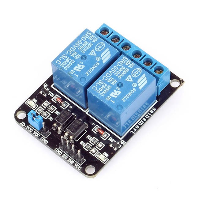
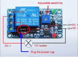

How to use relay modules to control AC devices?
A relay is an electrically operated switch to control high power/voltage or AC household devices using low-power signals from a microcontroller, etc. Many relays use an electromagnet to operate a switching mechanism mechanically, but other operating principles are also used. Relays are used where it is necessary to control a high power/voltage circuit by a low-power signal (with complete electrical isolation between control and controlled circuits), or where several circuits must be controlled by one signal. The most common types of relays that are used in the relay modules are the 12V SPDT (Single pole, Double Throw) type relays.
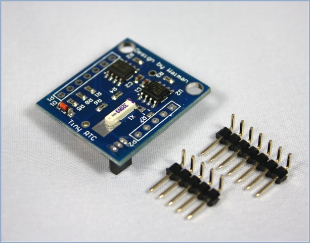
Arduino Tiny RTC I2C Real Time Clock
This Arduino Tiny RTC I2C module incorporates the DS1307 I2C real time clock IC and the 24C32 32K I2C EEPROM storage. What's more, it has a DS18B20 temperature sensor on board. All of this in a tiny package of 25mm x 28mm x 8.4mm. It comes with a LIR2303 rechargeable lithium battery, and a charging circuit is included in the module. When the temperature sensor is off, the RTC module can run for 1 year on a single charge.
This module is used for applications such as datalogging, timing applications ex. turning on the sprinkers at 4pm in the evenings. Since the module is self powered the time data is maintained even if the Arduino is powered off, allowing for building low power systems which can run for a long span of time without change of batteries.
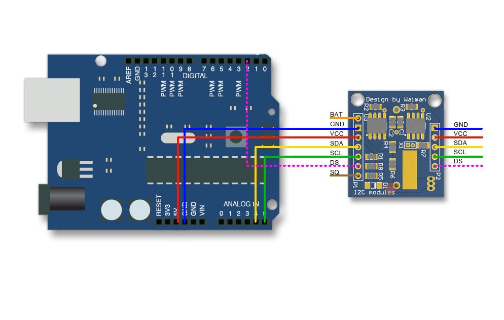
The most useful pins are duplicated from P1 to P2. If needed, the pin "BAT" can be fed into an ADC pin for monitoring the battery voltage. The pin-outs are explained below. Connecting "VCC" to 5 V will trickle charge the onboard battery.
Arduino Tiny RTC I2C Real Time Clock Pinout
|
| PIN | Description | Comment |
| BAT | Battery voltage | To monitor the battery voltage, or not connected |
| GND | Ground | Ground |
| VCC | 5V supply | Power the module and charge the battery |
| SDA | I2C data | I2C data for the RTC |
| SCL | I2C clock | I2C clock for the RTC |
| DS | DS18B20 Temp. Sensor output | One wire inteface |
| SQ | Square wave output | Normally not used |
The I2C wires "SDA" and "SCL" are the data line and clock line, they should be connected to the corresponding pins depending on the Arduino board.
|
| Board | I2C / TWI pins |
| Uno, Ethernet | A4 (SDA), A5 (SCL) |
| Mega2560 | 20 (SDA), 21 (SCL) |
| Leonardo | 2 (SDA), 3 (SCL) |
| 20 (SDA), 21 (SCL), SDA1, SCL1
Now it's time to connect relay module
SO first difine a pins of relay
1.VCC
2.GND
3.COM
4.signal
4.Normally open
5.normally close
Now connect a relay VCC to Arduino 5v.
Gnd to arduino GND.
Your motor pin connect a relay normally open.
And connect a arduino difine a any digital pin to relay signal pins.
And also connec a adapter nutral to relay com pin.
Also Aadptar anoither wire & motor another wire to jointed.
Now connect a RTC to Arduino
WE can use a only VCC,GND,SDA,SCA pins only.
Now connecta rtc VCc to arduino Vcc
And connecta rtc GND to arduino
Also connecta rtc sda pin to arduino A5 pin.
Also connect a rtc scl pin to arduino pin A4 .
|


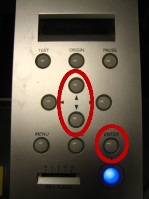
 So press button "SET KEYS"